Catalina 30 TRBS #2889 "Northern Light"
Rudder Reference Transducer (rudder position sensor)
for the Raymarine ST4000+ autopilot
The Raymarine ST4000+ Autopilot has provisions for an optional
rudder reference transducer. Rudder position information
augments autopilot performance by providing immediate
information about a rudder change, which is more immediate information
about position and rate-of-change than the data that can be obtained
from the autopilots compass, and a GPS (if attached.)
In certain conditions, the compass and GPS data exhibit a time lag
that is significant enough to cause "hunting" or overshoot that
cannot be corrected electronically in the setup configuration.
Mechanical
In my installation, I used an old rudder transducer made by VDO, and
modified it both mechanically and electrically.
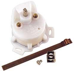
I removed the resistance assembly and installed a potentiometer whose
1/4" shaft extends upward through the housing through a
sealed bearing, and ends in a pulley instead of a lever.
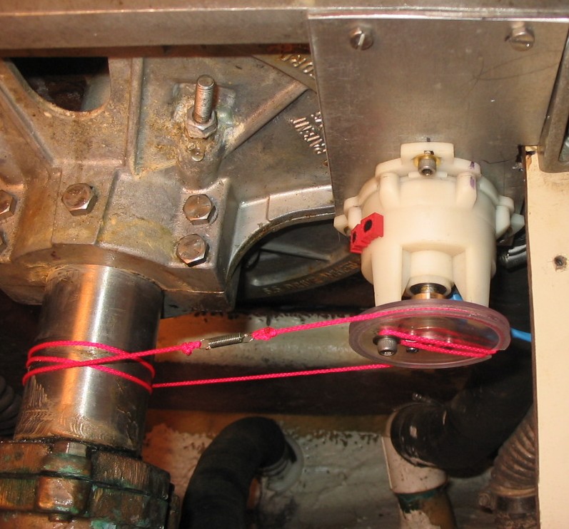
The transducer is coupled to the rudder shart using nylon
string and a spring to maintain tension.
(1/16" aircraft cable was too stiff for this scenario.)
Because my rudder shaft is 2.25" in diameter, I chose to fabricate
a pulley that was also 2.25" in diameter. It really doesn't matter
(within reason) what the shaft/pulley diameter ratio is as long as the
shaft doesn't force the transducer to rotate beyond it's limits. The
screw on the pulley prevents the nylon string from slipping.
What you can't see on the backside of the rudder
shaft is a stainless 6-32 screw that is threaded into the rudder shaft
that prevents the middle winding of the nylon string from slipping.
Electrical
The VDO sensor had a robust low resistance potentiometer bathed in oil, but
it's low resistance and it's lack of three terminals was suitable
for the ST4000+ autopilot. Thus, I modified the VDO transducer to
meet the electrical requirements of the ST4000+ autopilot rudder
reference input, which are (or appear to be):
- Rudder bar display, port 30 degree maximum indication: 2.0V
- Rudder bar display, rudder centered: 2.5V
- Rudder bar display, starboard 30 degree maximum indication: 3.0V
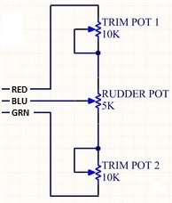
My modification removed the existing pot and installed a 5K pot
connected between zero and five volts (supplied by the autopilot,)
whose slider feeds back an analog voltage to the autopilot.
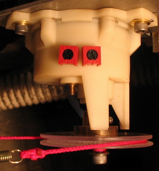
There is also a series 10K trim pot (red, screwdriver adjust) in series with each end of the 5K
pot that allows the exact calibration of the maximum rudder position on
my Catalina (approximately 60 degrees) to the display maximum
(30 degrees) on the autopilots screen.
Initial autopilot setup
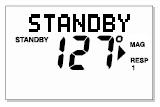
Without the rudder reference transducer, the ST4000+ autopilot
display appears as follows.
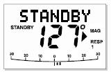
After installation of the rudder reference transducer, each time power is
applied the autopilot recognizes the presense of the transducer and
displays the rudder bar at the lower edge of the screen.
However, automatic transducer detection and rudder bar display won't
occur unless enabled in Dealer Setup.
This is an undocumented requirement from Raymarine. The setup
sequence is as follows...
- Install and connect transducer.
- Enter Dealer Setup mode by pressing & holding Standby for 14 seconds.
- Press +1/-1 simultaneously to get Cal Lock screen.
- Press Disp to get Pilot Type screen.
- Use +1/-1 to change type to a different pilot type, any type.
- Press Standby for two seconds to save setting and exit Dealer Setup.
- Repeat Dealer Setup mode, change back to correct pilot type (wheel or tiller,) exit Dealer Setup.
- Enter User Setup mode by pressing & holding Standby for 2 seconds.
- Press Disp five times to change to the Bar Selection screen.
- Press +1/-1 to select "Rudd Bar" or "Steer Bar".
- Press Standby for two seconds to save setting and exit User Setup.
- Power down and back up.
- Rudder reference transducer should now be detected and displayed on the screen
Transducer calibration
Once the rudder bar is displayed on the autopilot screen, the
rudder needs to be calibrated for center and limits.
- With the trim pots turned all the way to maximum sensitivity, center
the rudderpost and adjust the transducer so that the display shows
centered.
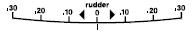
- With the rudder post turned to its maximum starboard angle
(whether or not that maximum angle is 30 degrees,)
adjust the trim pots equally to bring the display to
to it's 30 degree starboard maximum.
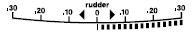
- With the rudder post turned to its maximum port angle,
check that the display indicates 30 degree port maximum.
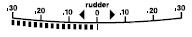
- With equal adjustment of the trimpots, and with recentering the transducer
as needed, the display should be able to be brought into calibration.
Final autopilot setup
One "acid test" that can be done to understand the performance of the
entire system, transducer, and settings:
under way and at speed, press +10 four times in one direction
or the other. If rudder gain (and by implication the rest of the system
and settings) is correct, this should result in a "crisp turn followed
by an overshoot of no more than 5 degrees" (from the ST4000+ manual.)