| ..................
|
Modified 04/13/09
This schematic and source code are intended
for demonstration purposes only.
They are offered "as-is". Use at your own risk.
Code and circuits (and more) are here.
Introduction
This circuit is a battery characterizer that applies a fixed load
to a charged NiCad or NiMH cell and measures milliamp-hour capacity
as it discharges.
There is no single load that can be applied to a battery to measure milliamp-hours.
It depends on the battery type, it's intended application, etc. This device is
simply one methodology that gives me a relative idea of the performance of
NiCad and NiMH batteries in my drawer. Discharge is approximately 200mA
which is approximately 0.1C for AA size cells or packs constructed
with AA size cells.
When NuMH¹ batteries come into being, I'll update this device to handle those
too.
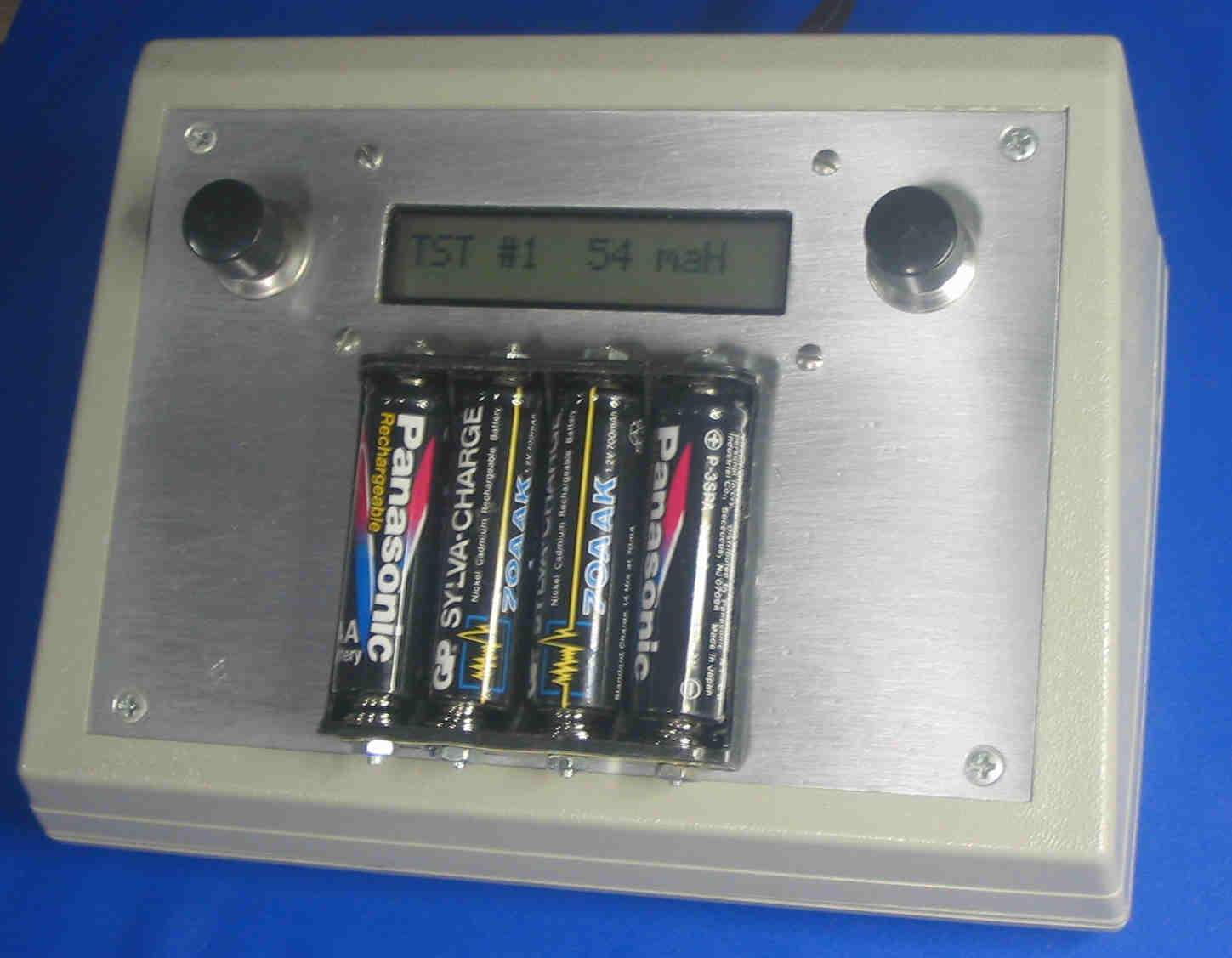
Click on photo to display full size image.
Features
- Up to five cells can be characterized at one time
- To avoid total discharge the load is disconnected when test stops
- Determines internal resistance and accumulated milliamp-hours.
Specifications
- Power: 8-16VDC at ~100mA
- Sampling: once per minute
- Load 0.1C (~200mA)
Operation
Connect an 8-16VDC power supply to the battery characterizer.
Insert the cell(s) or connect the battery pack to be tested.
After a charged cell is inserted in a socket, the unit waits for the
voltage to stabilize (to avoid false measurements during first contact,) then the internal resistance
is measured for later display when the cell test is complete.
Thereafter, the cell is placed in TEST mode, the load is turned on,
and milliamp-hours are accumulated. When the cell voltage falls
below the cutoff voltage (1.0V per cell,) TEST mode is terminated and the load is turned off.
DONE mode thereafter displays
the total milliamp-hours and starting internal resistance until
the cell is removed from the socket.
Socket #5 is designed for multiple-cell packs. The number of cells is calculated
from the initial measured charged voltage and is in turn used to calculate
the proper cutoff voltage by dividing by the nominal 1.2V per-cell voltage.
TEST screen
The TEST screen displays "T" and the cell number
and it's accumulated milliamp-hours.
DONE screen
The DONE screen displays "D" and the cell number, the
total accumulated milliamp-hours (rounded to the nearest 100,) and
the internal resistance (rounded to the nearest tenth) of the charged cell at the beginning of the test.
DETAIL screens
The DETAIL screens display various measured and calculated parameters during TEST and DONE cycles.
This set of screens is invoked by pressing the button for longer than a half second. The various
screens sequentially appear for two-seconds each. DETAIL mode is ended
when the complete set of screens has been displayed, or if the button is pressed momentarily.
During TEST mode
|
| In DONE mode
|
|
|
|
|
|
|
|
|
|
|
|
|
|
|
|
|
|
|
|
|
|
|
|
|
|
|
|
|
|
|
|
|
If all sockets are empty, the display shows a message to that effect.
Operational notes
- It's assumed that the battery pack to be tested is fully charged.
- The pushbutton cycles the display through the status screen of each cell.
If the pushbutton is not pressed for ten seconds or more, the
display will cycle every two seconds to the next cell in succession.
Empty sockets are skipped.
A cell that measures less than 0.4V is interpreted as an empty socket.
- The internal resistive load is disconnected when
the battery discharges to the cut-off voltage (1.0V.)
This prevents discharging the cell down to zero volts.
For a multi-cell pack this precludes the possibility of
reverse biasing and damaging a weak cell in the pack.
- Repeated tests of the same battery can yield maH results
that vary 20% or more...it's highly dependent on actual charge.
- If the button is held down for more than four seconds, the
system will go into reset mode, just as if the power were first turned on.
Technical Reference
HARDWARE
- The PIC is configured for power-on delay and brownout reset to guarantee
proper resetting of the PIC.
- R1 and R2 form a voltage divider for testing battery packs of multiple
cells. Whatever the divider resistors are, they should be several tens of
kilohms, divide the voltage down to 5.0V (max,) and the ratio should be
inserted into the C code before compiling.
- If using my preprogrammed PIC without specifying specific values
for R1, R2, and Vdd, since I have very specific values for R1 and R2 in my own unit
and you undoubtedly won't have my exact measured values, do the following...
- Do this instead...use a 10K fixed resistor for R2.
This will not only divide, but also limit current into
PIC pin 7 if the voltage on that socket is from a high
voltage cell of some sort. Use a 10K multi-turn pot for R1.
- Once built, you can calibrate the socket five voltage to
read accurately on the screen.
- Since the 5V power supply is used as the Vreference for the PIC's
ADC, if your power supply is something other than that, the voltage
readings will be off a bit and won't match what you'd read on your
DVM. Try to find a voltage regulator that gets it quite close to 5.00V.
- Channels 1-4 have 100K resistors across the battery socket. That
prevents the ADC inputs from floating and forces empty sockets to zero volts.
- Display contrast is controlled by R3 and R4, or insert a 10K pot instead.
- Loading is done by the 5-ohm 1/2W and 20-ohm 1W metal film resistors.
These values were selected to discharge at approximately 250mA.
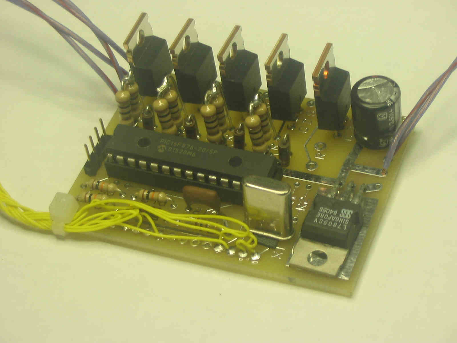
Click on photo to display full size image.
- For best accuracy, measure the resistors and insert their
real values into the software. Measure the voltage drop across
the FETs and calculate their resistance and insert that into the software.
- Also for best accuracy, ensure that the VDD in the software matches
the measured VDD in the hardware. Otherwise voltages will not be
displayed accurately. This is because VDD is used as the reference voltage
for the ADC in the PIC.
- If you don't want to deal with actual values for R1 and R2, simply make
R1 a 10K pot and R2 a 10K fixed resistor. Adjust the pot to make socket #5
voltage read correctly.
- The 1-line, 16-character LCD display I used is made by Optrex
obtained from MPJA. Similar LCDs are
sold by DigiKey and Crystalfontz, listed in my main PIC page.

Click on photo to display full size image.
SOFTWARE
- Basic sequence: The main loop code sets up the display, ADC, clock, and
variables after which occurs an endless loop of checking switches,
sampling, and displaying to the LCD screen.
Timing and switches are handled by a 31mS interrupt.
State is controlled by a simple state machine.
- During test, the cut-off voltage must be reached for a full minute before
testing is automatically stopped. This avoids early stops due to electrical
noise at the ADC input or due to poor connections to the battery pack.
- The per-cell cutoff voltage is set by a #define statement in the C code.
For multi-cell battery packs, this cutoff voltage is further multiplied by
the number of cells, which is determined by dividing the measured voltage
by the nominal cell voltage (also a #define statement.)
- Actual load resistor values, FET resistance value, and other
key parameters may be inserted at the top of the code.
|