Modified 12/03/06
Code and circuits (and more) are here.
Introduction
This microprocessor-based combination lock controls an electro-magnetic lock unit for an entry door.
Features
- A 4x4 keypad is located outside the door.
- The master combination will open the door, as well as allow programming of up to four transient combinations, the illumination duration, and lock solenoid duration.
- The lock solenoid is activated for a programmable time (initially one second) when the correct combination is entered on the keypad, or when the MANUAL pushbutton is pressed inside the building.
- A DISABLE switch, located inside the building, is useful for day use when the building is occupied. Pressing any key on the outside keypad will active the lock magnet.
- Any time the lock solenoid is activated, the illumination relay is activated for a programmable time (initially five seconds.) The relay can control sidewalk or keypad illumination lamp connected to an appropriate voltage.
- The programmed values are stored in the F84's EEPROM. Setting a value to all zeros deactivates it.
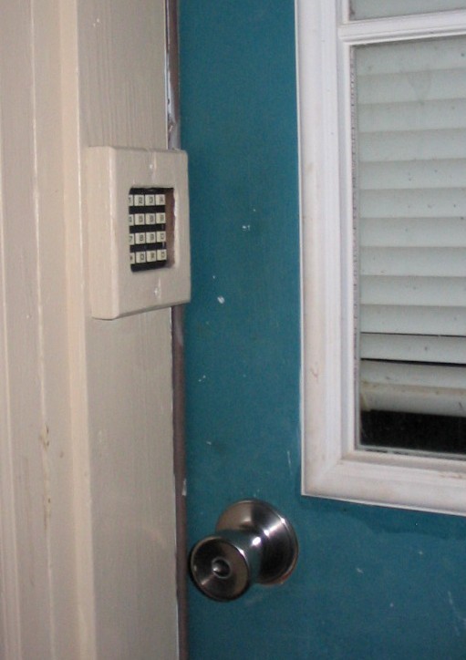
Click on photo to display full size version.
Operating Instructions
- the master combination is '083941'
- all combinations are six-digits; all times are two-digits
- four transient combinations and two times may be programmed
- to enter a transient combination, press within one-second
after entering the master combination:
- 'A' to enter 1st transient combination
- 'B' to enter 2nd transient combination
- 'C' to enter 3rd transient combination
- 'D' to enter 4th transient combination
- and then enter the transient six-digit combination
- to enter a time, press within one-second
after entering the master combination:
- '#' to enter two-digit lamp ON time (default is 15 seconds)
- '*' to enter two-digit lock ON time (default is 01 second)
- and then enter the two-digit time
- setting a combination to "000000" or a time to "00" will deactivate it
- if a wrong digit is pressed, resets after five seconds
Technical Details
HARDWARE
| PORTB.4 | Illumination lamp relay | high-active |
| PORTB.5 | DISABLE switch to allow any key on the keypad to activate the lock | low = disable |
| PORTB.6 | MANUAL open switch | low = open |
| PORTB.7 | lock magnet output | high for one second |
- The keypad connector is: C0 C1 C2 C3 R0 R1 R2 R3
- The internal "weak" pullups on PORT B are used; the external keyboard pullups may be omitted.
- The power supply illustrated in the schematic is a switching power supply, but any simple 5 volt supply may be used, such as a 7805, 309, etc.
- The output triac can be anything that will handle the voltage and current of the lock solenoid. The MAC224 is simply what I had in my collection. Likewise, the transformer must be able to supply enough current at the correct voltage for the lock solenoid.
- Optical isolation is provided by a 6V lamp and 70-ohm CDS photocell. Alternatively, you can omit these components and the triac by substituting a 5V relay for the "6v20mA LAMP" and using the relay contacts to drive the lock solenoid.
- The MANUAL switch can be omitted and the PIC pin left open.
- The DISABLE switch can be omitted and the PIC pin left open.
- As a test of the F84 itself, if you connect +5V to pins 4 & 14, connect ground to pins 3 & 5, pullup with 10K pins 6,7,8,9, hook the 4MHz crystal to pins 15 & 16, and then ground pin 12 momentarily, you should see pin 10 (the lamp output) go high for the illumination duration (initially five seconds) and pin 13 (the lock output) go high for solenoid duration (initially one second.) Also, ensure that you have some sort of 4MHz waveform on the crystal.
- Do you need capacitors (specified by Microchip) on each side of the crystal? Technically yes, to ensure that the PIC will start over all voltage, temperature, and manufacturing variations.
SOFTWARE
- The watchdog function is used to ensure successful reset during powerline anomolies.
- The software loops to look for the first digit of the combination if an incorrect digit is entered or if a digit is not entered within the programmed illumination duration.
- The code sets the 16F84 configuration word for: Watchdog on, CP off, power up timer on, and crystal oscillator. The configuration word (3FF5) is embedded at the end of the hex file at address 400E. Remove it and configure the PIC manually if your programmer has trouble with it's presence in the hex file.
DOOR SOLENOID
- Door solenoids run from $25 to $150. Graybar, a U.S. nationwide electrical supplier, has a good selection of solenoids manufactured by Edwards, called "Door Openers", around $36 . Graybar is 800-825-5517 with local Graybar distributors all over the U.S. (If you visit a door supplier, the prices will be much higher!)
- Another possible actuator is the radio-control airplane servo. Depending on size, they have pretty good torque and accomplish most of the mechanical aspects for you. The middle size (standard) is always the cheapest, around $9-12. They are easy to drive with PIC's or microprocessors in general. Some of my other projects on this site will provide software examples of their drive signals. Tower Hobbies is a good supplier, 800-637-4989, http://www.towerhobbies.com.