Modified 11/11/12
|
This schematic and source code are intended
for demonstration purposes only. They are offered "as-is". Use at your own risk.
Code and circuits (and more) are here. |
Introduction
This circuit is a data logger that records voltage samples at specific time intervals.
I've used it to record the voltage discharge curve on NiCad battery packs. The data file can be dropped into a spreadsheet and plotted.
I've also used it to record the amount of time a possibly defective refrigeration unit was running during a 24-hour period (using a current clamp and full wave bridge.)
Features
- Input range: 0-5VDC and 0-14VDC.
- Capacity: 8192 samples
- Time interval is settable from 1 to 65535 seconds
- Dump to display or 9600 baud dump via RS232
- Key switch locks front panel pushbuttons during logging
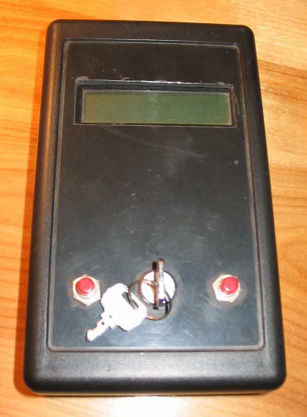
Click on photo to display full size version.
Specifications
- Power: 8-12V
Operation
- Provide +8-14VDC power for the data logger. NOTE: first remove any voltage or signal that is connected to the datalogger input or it may partially power up the microprocessor even without the power applied and cause it to come up in an unknown state.
- Set up the source of voltage you will be logging. For instance, if you are using a clamp-on current transformer (Fluke and others) to monitor the current used by a motor, you must convert the AC output to DC using a bridge rectifier and small capacitor such as 0.1µF. An appropriate parallel resistor will allow you to scale the DC voltages to a meaningful and proportionate value between 0 and 5 volts. Or, if you are measuring temperature using a thermister and resistor, connect the thermister/resistor between the +5V AUX OUTPUT and GND jacks, and connect the center to the ADC input jack.
- Generally speaking, the MENU/DEC switch
cycles through various menu options and the
SELECT/INC switch selects an option.
The buttons auto-repeat approximately two times per second.
The options are:
- START - start data logging
- STOP - stop logging
- STATUS - display the time interval and sample count
- RESET - reset the sample count to zero
- INTERVAL - set the time interval (1-65535 seconds)
- RANGE - set the voltage range to 5V or 14V
- VIEW - view the data samples
- DUMP - send the data samples out RS232 at 9600 baud
- Ensure that the logger is in IDLE mode. If not, press MENU/DEC enough times to display STOP and press SELECT/INC.
- Go to the INTERVAL option and set the time interval. Use SELECT/INC to increment the digits between 0 and 9, and use MENU/DEC to cycle through all five digits.
- Go to the RANGE option and set the range. Use MENU/DEC to cycle between the ranges, and use SELECT/INC to select the displayed range.
- Go to the RESET option and press SELECT/INC to clear the data memory.
- Go to the START option and press SELECT/INC to begin logging. The STOP option will be displayed. Pressing SELECT/INC at any time will stop logging and go back to the start screen.
- During logging, RUN is displayed rather than IDLE, and the STATUS, VIEW, and DUMP options are available.
- In the VIEW option, SELECT/INC increments the data sample number and MENU/DEC decrements the number. Press both keys simultaneously to end VIEW mode.
- In the DUMP option, press both keys simultaneously to end DUMP mode early.
Technical Reference
HARDWARE
- The 1N4001 diode provides reverse current protection.
- The "+5 AUX OUTPUT" jack provides +5V to measurement devices such as thermistors, etc.
- The 1M resistor at the datalogger input keeps the input from floating and discharges any capacitance in an input device that might accumulate charge and slowly build input voltage. The 10K series resistor at ADC input RA0 is a current limiter in the event of input voltages that are outside the 0-5V range. RC2 is set to a float condition by the software to select the 5V range. For the 14V range, RC2 is set to output a low, connecting the 10K (14V calibration) pot as a voltage divider with the 10K fixed resistor.
- The key switch is not necessary. It's included only to keep inadvertant button pressing from doing anything destructive during a data logging operation. Wire across it if unused.
- The MAX235 and DB-25F can be left out of the unit if the RS232 dump is not necessary.
- The LM340T regulator can certainly handle higher inputs that 14V but heat sinking becomes rather significant.
- The MCP130315DI Supervisor is a power-on-reset device to guarantee proper resetting of the PIC. You may leave it out and connect the PIC's MCLR directly to +5V if resetting does not present difficulty. Alternatively you may use the brown-out detect feature in the 876 (BOD bit in the configuration word.)
- The SEL0 and SEL1 inputs are unused at the present time.
SOFTWARE
- The external EEPROM memory size is 16,384 eight-bit bytes. This allows 8192 samples because 16 bits per sample are required to hold the 10-bit ADC value. The #define EEPROM_SIZE is the byte size and must be changed in the source code to recognize other memories.
- Once running, logging continues regardless of the particular screen being displayed. The one exception to this is DUMP during which the timer interrupt is disabled.