Modified 05/20/05
|
This schematic and source code are intended
for demonstration purposes only. They are offered "as-is". Use at your own risk.
Code and circuits (and more) are here. |
Introduction
This is a tachometer for a diesel engine in which there is no tach pulse available because there is no spark ignition system. Instead, a pulse is taken off the "tach" output of the alternator (simply a wire connected into one of the three stator windings.)
Features
- Pulley ratio and number of poles can be set in code (default is 1.0 and 6)
- Pulse period is measured with microsecond resolution (RPMs increment by 1's)
- Period is averaged over 20 samples
Theory
This is an example of using the CCP (Capture-Compare-Pwm) module within a PIC. This module is set to capture mode in which the value of Timer1 is captured on every rising edge of the 16F628 CCP1 input (pin 9.) Because Timer1 is increments once per microsecond (4MHz crystal,) pulse period in microseconds is simply the number of counts that is captured each time. Simple math then converts pulse period into RPMs. Using the CCP module to measure period is much better than counting pulses for some fraction of a second and then multiplying by some factor to get RPM's, which would mean that RPM's would jump by some rather coarse increment.
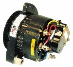
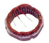
After examining the various ways to pick off an RPM signal from my diesel engine, I rejected the more difficult options of installing a magnetic or optical sensor on the crankshaft, and opted instead to pull the alternator apart and connect a wire into the three-phase delta-connected stator to bring out an AC signal.
The pulley ratio is "crank pulley diameter / alternator pulley diameter".
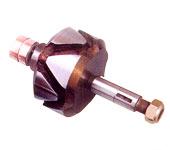
The number of "poles" in the alternator is the count of separate poles on the rotor. Each of the two halves of the rotor in my particular alternator has three fingers
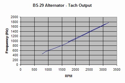
Alternatively, one may buy a diesel alternator, such as the BS-29 at "The Battery Shack" in Florida. It's alternator terminal exhibits the following frequency/RPM response.
Specifications
- Power: 5VDC
- Min RPMs: 400
- Max RPMs: much higher than you'll ever attain in a diesel!
Operation
TACHOMETER |
The single screen is illustrated above. If pulses become too slow, such as when the engine is off, "0 RPM" is displayed.
Technical Reference
HARDWARE
- The pulses from the alternator should have an amplitude of at least 3V. Positive voltage excursions should not exceed +5.3V. Negative voltage excursions should not go below -0.3V. Square waveshape is best. The filtering scheme in the schematic achieves this.
SOFTWARE
- Be sure to appropriately set the #define statements for PULLEY_FACTOR and ALTERNATOR_POLES in the code.
- This a simple design, but the floating point arithmetic bumps the program code size and consumes more than 50% of the available 2K program memory!
- An example in which this code is embedded in a larger system can be found here.
CORRECTIONS / UPDATES
- v1.0 - first release