Modified 03/10/2017

About the LCD displays used
in most of these projects
Hardware
- Any character-based LCD display that has an industry-standard HD44780-compatible controller may be used. These displays have eight data pins, plus an EN pin, RS pin, and R/W pin.
- The characters are addressed sequentially. That is, the first character on the first line is located at address 0, and addresses proceed upward to the end of the line. The second row likewise starts at a specified address (but not immediately following the first row's last address) and proceeds upward. Please note that certain HD44780-compatible displays have an odd addressing scheme whereby the character address jumps in the middle of the line. For instance, in a 16-character display, the first eight characters are located at addresss hex 0-7, and the last eight are located at addresses hex 40-47. (Send these displays back to your supplier...they are really useless!)
- All of my devices use four-bit data mode, meaning that only four of the LCD's eight data bits are used, D4-D7. Thus, the PIC interface requires only six wires (four data, RS, ENable) plus power, ground, and contrast voltage. A six-wire bus is nice for the smaller PIC's because it leaves the remainder of the port pins for other uses. My projects tie R/W (pin 5) to ground which puts the display memory permanently in write mode.
- The basic connections are illustrated in the schematic below, but
the code example allows you to select any PIC port bits you desire.)
- I have successfully used the PWM output pin (on PICs that have them) for driving the contrast pin on the display. This allows the display contrast to be adjustable by software. The default setting should probably be zero duty cycle so that the PWM pin sits low which causes full contrast. That way you will at least see something upon power-up and can adjust contrast from there. There needs to be a series 1K resistor between the PWM pin and the contrast pin 3 on the display. Connecting a 4.7uF capacitor from display pin 3 to ground with then smooth the PWM pulse waveform to DC.
- "Supertwist" displays have wider viewing angles than others. LED backlighting is preferable to electroluminescent backlighting because no HV supply is necessary. However, for a large display (such as 1.5" x 4") I've found that the backlighting can draw a half amp! If it is desired to switch such backlighting off and on, logic-level N-channel MOSFETs (such as IRL520N) make a good switch such as shown in the schematic above.
- Examples of LED backlight supertwist displays are:
- LCM-S01604DSF from Lumex available as part number 67-1761-ND for $28 from DigiKey.
- Crystalfontz, among other backlit displays, has the 16x2 CFAH1602C-YYH-JP for approximately $12.
Software
- This code example matches the
pin connections in the schematic above.
(Change your code and connections to any port bits you desire.)
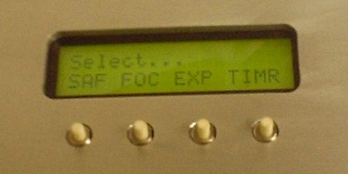
The code produces on a 2x16 display the following image...
TEST #1
2nd test - You'll see this code instantiated at the bottom of the C code of any of my devices that have displays, and calls to that code can be seen throughout those C code examples.
- This code is pretty stable...that is, I use it everywhere. I define
a few items at the top using "#define" statements, and insert the six subroutines
at the bottom, and it works with no problem. Someday I should put these
LCD subroutines in a separate include file but haven't done it yet.
Debugging
You've applied power but see nothing...
- The presence of backlighting doesn't ncecessarily indicate that the display has power...sometimes the backlighting pins are separate from the power pins.
- If the display is truly powered up, even if no coherent data is being supplied you should at least see that there is a background "raster," that is, each character should have a gray or darker background. Be sure to adjust the contrast control to see this raster! If misadjusted, there's no hope of seeing characters. Everything could be working normally but if the contrast control is misadjusted you will see nothing! The voltage at the contrast pin (3) is usually between 0 and 1 volt.
- If you have access to an oscilloscope, depending on what the code is
doing, you should see data on the four data pins. Initially, you might
write something to the display every few hundred milliseconds so you have
something to probe and view, such
as:
LCD_Init(); while ( 1 ) { LCD_SetPosition ( 0 ); printf ( LCD_PutChar, "TEST" ); delay_ms ( 500 ); } - Don't forget to check with an oscilloscope that the crystal is alive and running at the correct frequency.
- The initial debug seems tedious but stick with it. Once your display routines work, they work forever and you won't have to re-visit this code.
- One problem I encounter with LCD displays is that if the power glitches, the display will show random characters and not work properly until re-initialized by software or power is dropped and restored. I haven't figured out a way to automatically detect this by software. I believe most designers work around this by constantly rewriting the entire display from a memory image.