Modified 08/15/07
This schematic and source code areintended for demonstration purposes only.
They are offered "as-is". Use at your own risk.
Code and circuits (and more) are here.
Introduction
This program is a simple combination lock that I designed for an old Sentry® fire safe that was given to me without any lock electronics. I created a front panel with a keyboard and microprocessor with a six-digit combination sequence.
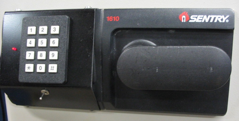
Click on photo to display full size version.
Details
The LED flashes to show it's alive after power is applied.
The lock solenoid requires 6VDC at approxmately 2 amps. Given that a small 9V battery is used and wouldn't easily provide that current for very long, I used the PIC's PWM output to vary the current in two phases:
- It starts with a 30mS "pick" phase that delivers full current by providing a 100% duty cycle to the FET driver which puts a solid 9V across the solenoid.
- That's followed by a "hold" phase of 1.4 seconds at a reduced duty cycle that reduces current to significantly less.
The initial combination is "123456". Regardless of any immediately prior key sequence, when that correct key sequence is entered and completed, the lock solenoid is actuated for 1.5 seconds. If a key isn't pressed for two or more seconds, the firmware resets to again look for the first digit.
Caveats
Since this circuit is battery powered, some way is required to turn on the battery when needed. I used a toggle switch below the keypad to accomplish this, but more innovative methods would be more elegant. For instance, one could employ some sort of mechanical cover over the keypad whereby lifting the cover would actuate the switch to connect the battery.
If the microprocessor, etc, is located on the outside of the safe, it won't be as secure as one might think, because all one would need to do to gain access would be to remove the front panel and apply 6VDC to the wires of the internal lock solenoid. To make it more secure one could bury the microprocessor and FET device inside the door, but if there was a failure you'd have to cut open the safe to gain access!
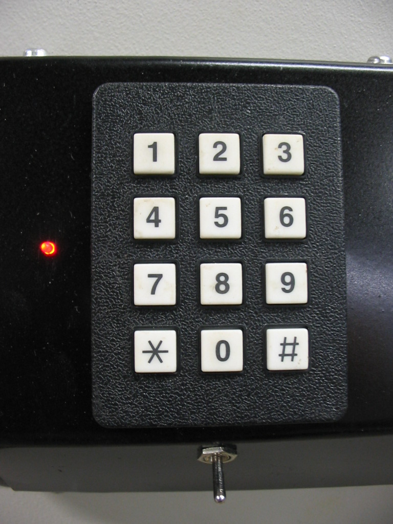
Click on photo to display full size version.
Technical Reference
HARDWARE
- .
SOFTWARE
- .
CORRECTIONS OR UPDATES
- v1.0 - first release